![[Image of the location of the screws]](screws.jpg)
To open the case, you have to remove five screws using the philips driver: one on the left side (seen from the back, this one was already missing on the camera I got off ebay), three on the bottom, and one hidden under the rubber cap over the DIGITAL and DC IN plugs. A sixth screw is holding the cap for the buffer battery, which I removed, too. This one is smaller than the others, so don't confuse them.
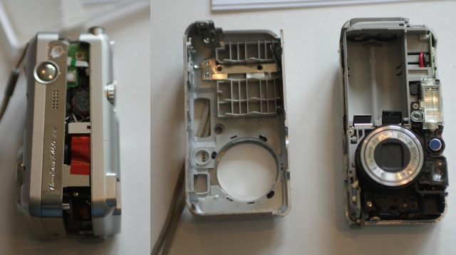
Now you can remove the front cover by sliding a small screwdriver between the two halves along the top of the case.
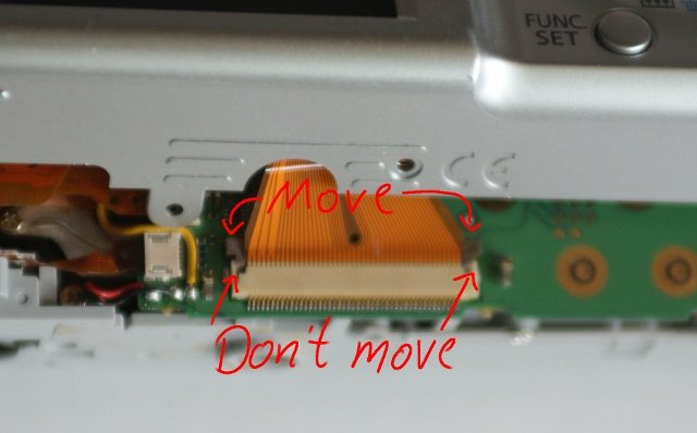
Removing the back cover is a bit more difficult, use a screwdriver lift the top right corner (actually top left if looking from the front) of the main circuit board out of the case and move the interior parts sligthly to the left so the AV-plug does no longer hold the back cover in place. Be careful, because the Display is still connected via a flat ribbon cable. Carefully open the brown part holding the ribbon cable on the main circuit board (do not try to move the lighter colored parts, they will snap).
![[Image of the exposed main circuit board]](main-board.jpg)
The next step is to put some insulating tape over the two contacts marked M+ and M-. The are the connectors for the capacitor powering the flash. I have seen claims that theese capacitors contain enough charge to kill a human. While I cannot testify to the accuracy of these claim, I can testify to the fact that you do not want to accidentally touch these two point. There are a few more point where the voltyte of the capacitor is exposed, but M+ and M- are the most annoying among these.
Now you have to remove the main circuit board from the battery compartment. Remove the two screws on the main board. A sligthy tricky operation is the removal of the eject lever for the SD card. First remove the screw in the bottom right and the black piece of plastic held by it. Now carefully remove the lever, without letting the tiny spring jump away. Now remove the screw at the bottom and the piece of metal held by it (it may be glued in place, but comes off easily if moved a bit).
![[Image of the front side after
removing most parts]](loose-front.jpg)
Finally remove the screws holding small board with the power switch on the top and the flash front side and move both parts as well as the red and black cables up. I also removed the viewfinder (held in place by two screws) and the AV plug (one screw) and loosend the remaining flat ribbon cables (remember, move the brown parts, not the light ones).
![[Image of the partly lifted main board]](under-main.jpg)
The lens/sensor unit is fixed with three screws. One is easily accessible on the bottom left, the other two require to bend the mainboard up and remove the red piece of adhesive film (and be carefull to stay away from the connectors of the large capacitor).